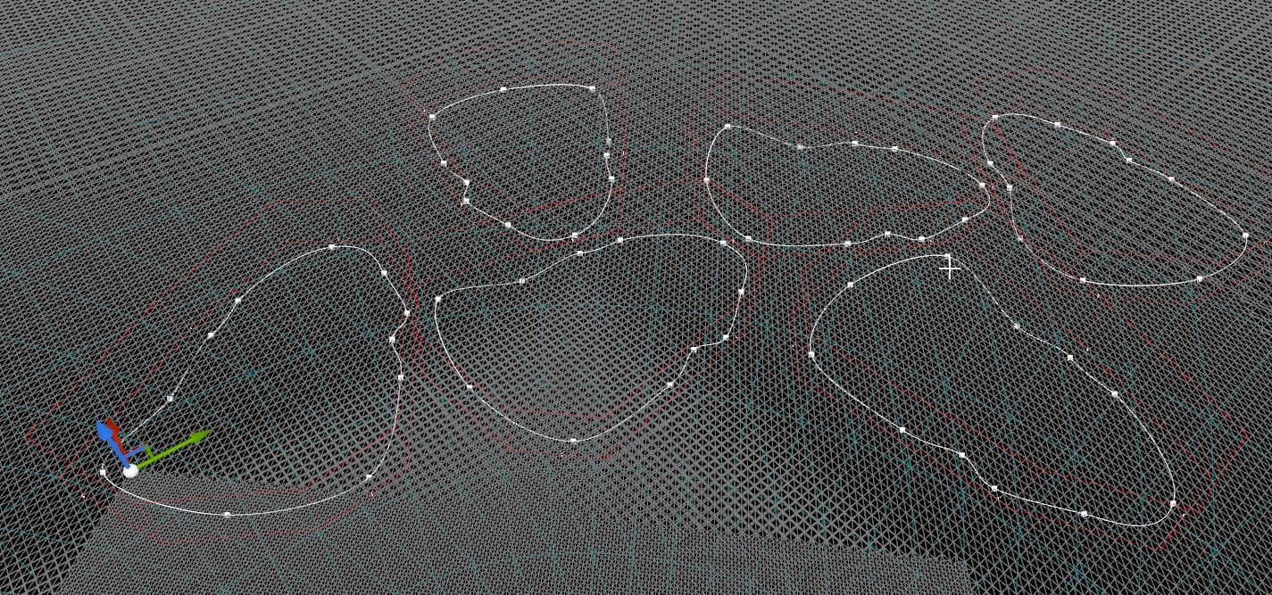
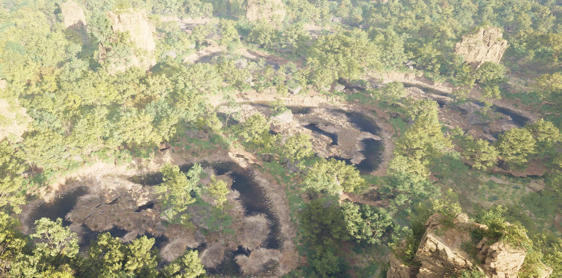
In this tutorial, we’ll be creating this:

This tutorial build on these two existing tutorials:
Go through those first, if you haven’t done so already
Download and load up the Electric Dreams project
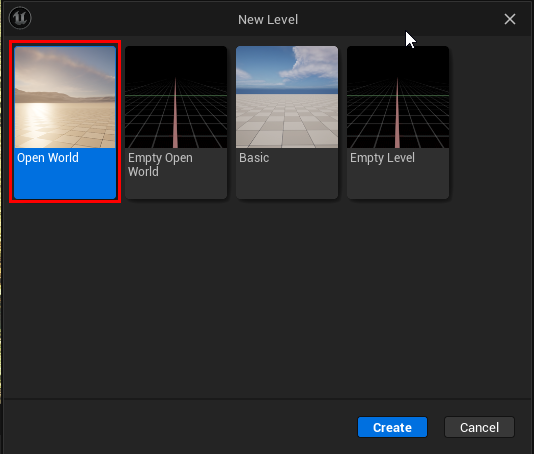
Create a new Open World level
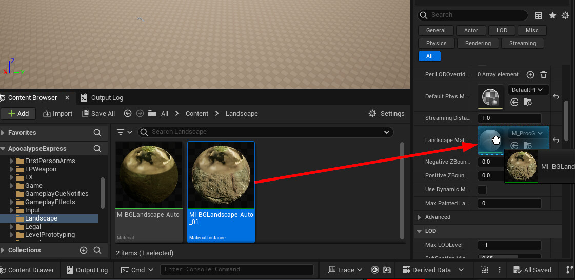
Assign the landscape material
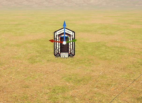
and drop in a Dungeon Actor and reset the location to ground level (e.g. 0,0,0)
Set the builder type to SnapMap

Module Creation
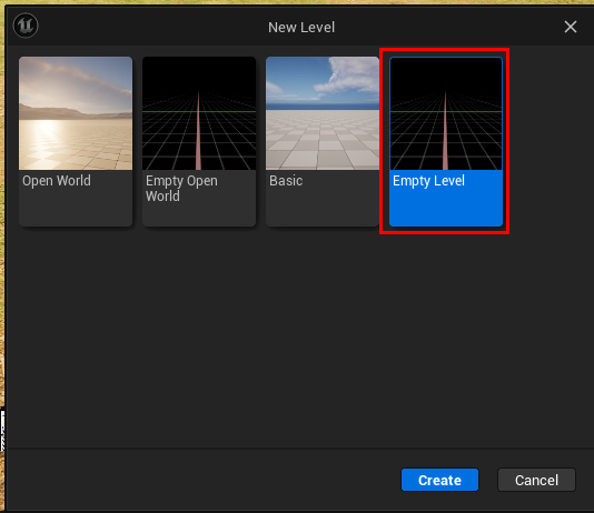
We’ll create individual modules, like you see in the video above. Save this level then create a new empty level for our module
NOTE: Modules are rooms that are stitched together using the SnapMap builder
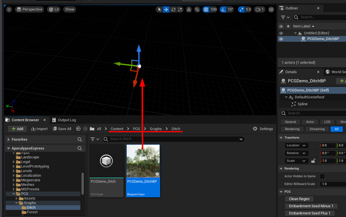
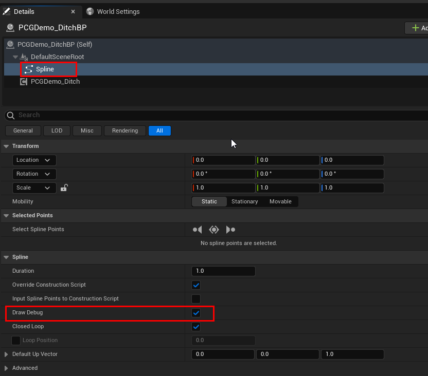
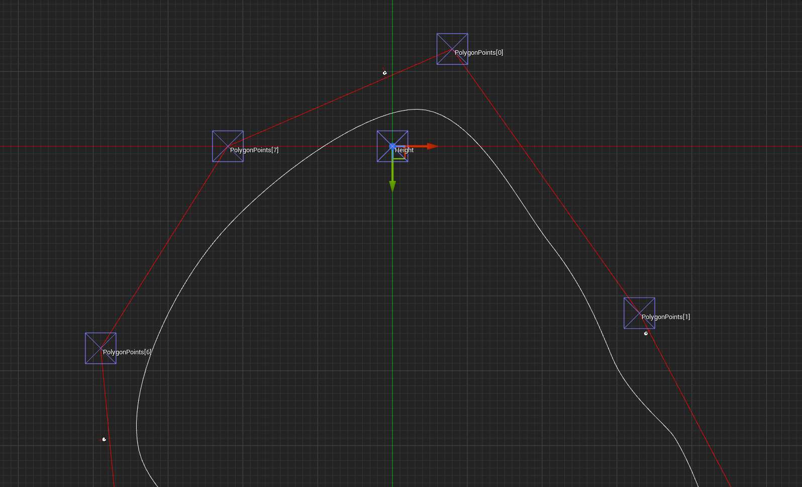
Select the ditch blueprint and select the Spline component, so you can visualizae and modify the spline shape

With the Spline component selected, enabled “Debug Draw” so you can view the spline shape even when the ditch actor is not selected. We’ll need this for propertly aligning the connections
Snap Connection
Create an empty snap connection asset.

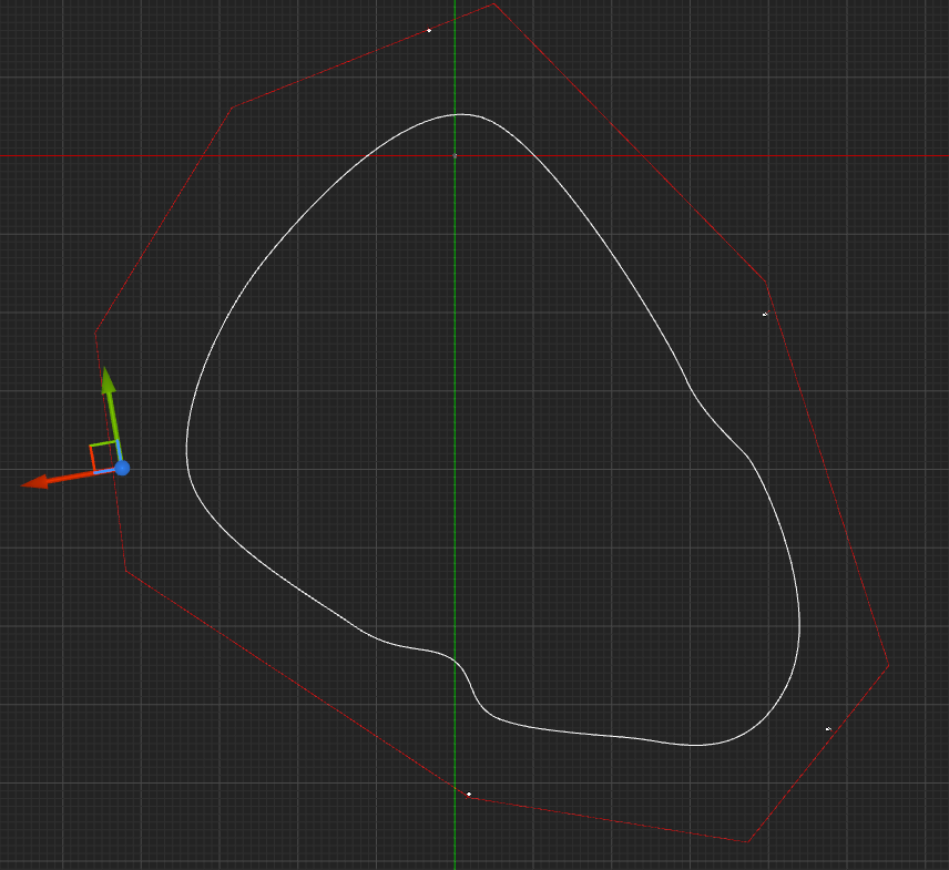
Drop this connection in a few places around the spline. Don’t keep it too close to the spline as the art assets that the ditch blueprint creates around this spline are a bit further away. Place them like this:
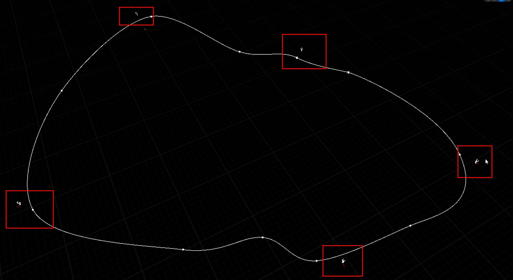
Make sure the red connection arrows are facing outwards
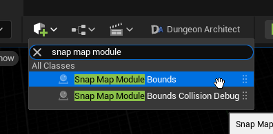
Next, drop in a Snap Map Module Bounds actor
Add more points as needed and wrap it around the spline shape. Keep it a bit further away from the spline, as the ditch spline creates the assets outside the spline shape. Make sure the bounds are near the snap connection actor

You may switch to the top view to align everything
Save the module level
Module Database
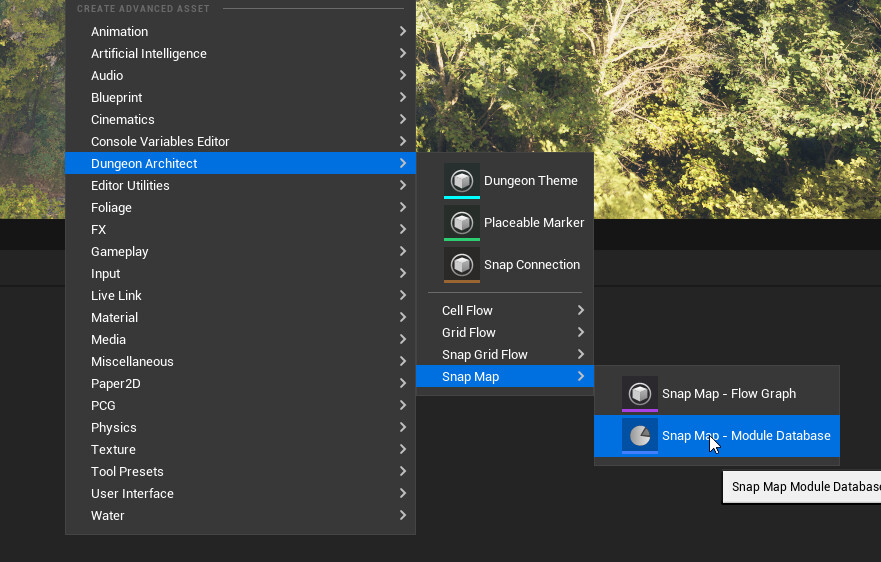
Create a SnapMap module database and register this module.

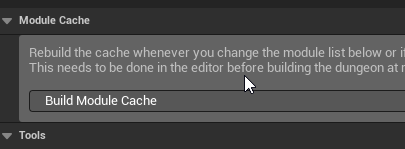
Build module database cache
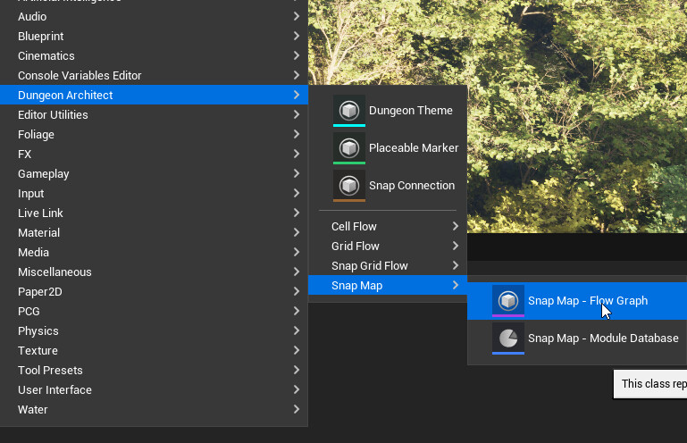
Flow Graph
Create a SnapMap flow graph. These are rules for stitching the levels. Right now we have only one module, registered under the name “Room” in the module database created above
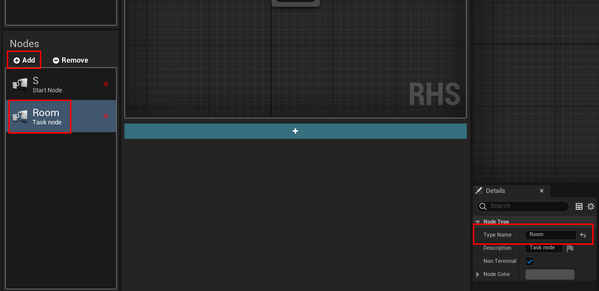
Add a new node and name it Room. We name it Room because we’ve registerd our module in the ModuleDB with this name
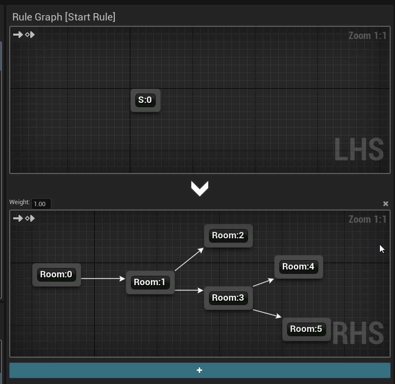
Select the Start Rule and add two Room nodes on the RHS graph and connect them up
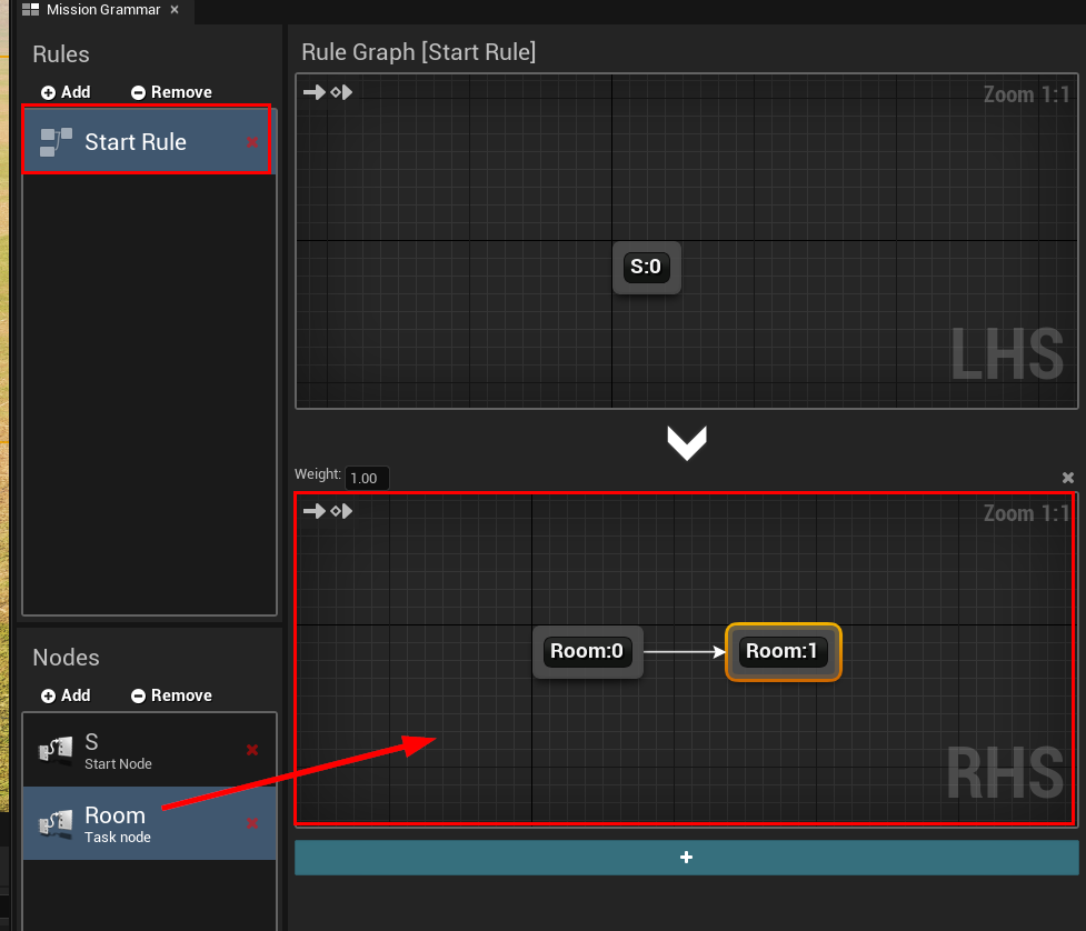
This will connect two rooms together. We start with a small graph to make sure the connection setup works. Then we move to larger graphs
Setup Dungeon Actor
Open up the first map we created and select the Dungeon Actor
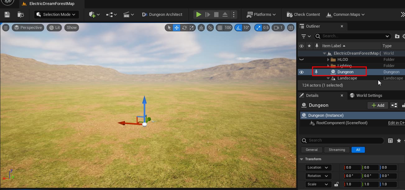
Change the Builder Class to Snap Map

Then assign the assets we created
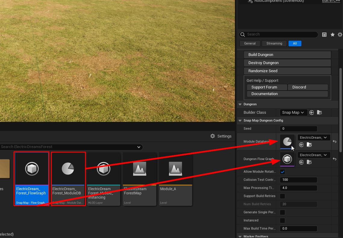
Click Build Dungeon, it should stitch the two modules together

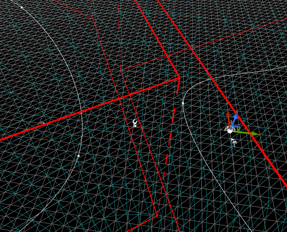
Troubleshoot
If it didn’t build, make sure the connection points are not too far inside the module bounds
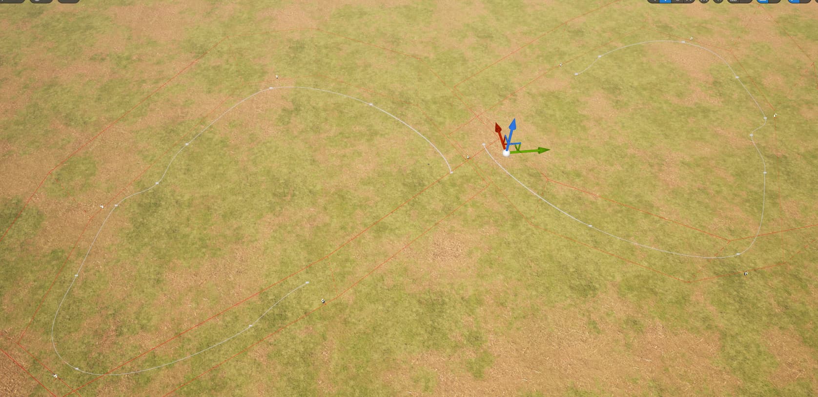
This is how a successful stitch looks like
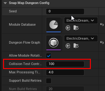
Either update your connection point positions and rebuild your module database (important!) or increase the collision tollerance to a higher number, this is the amount of overlap the system would tolerate
Improved Flow Graph
Now that we have this working, open up the flow graph and add a more complex rule
Build the dungeon
Randomize, Click Build


Generate Persistent Level
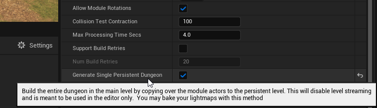
After we generate the dungeon, we want to pass this spline information to the PCG system. So we don’t need level streaming here and everything needs to be generated in the current persistent level
Select the dungeon actor and enable GenerateSinglePersistentDungeon
PCG Post Build Setup
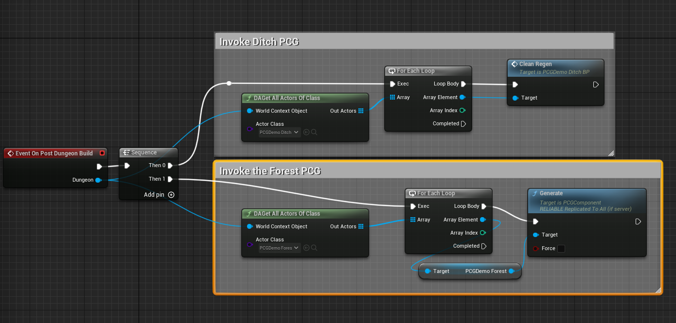
After we spawn our rooms into the world (which are ditch splines) We want the PCG system to build everything. Lets create a post build event for it
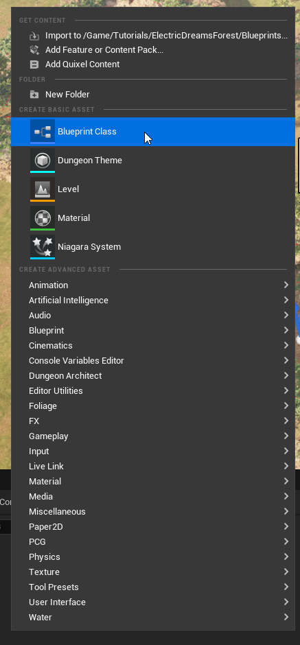
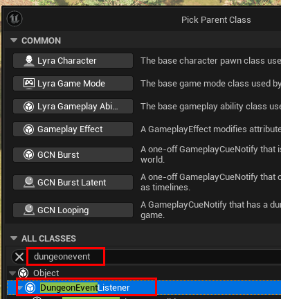
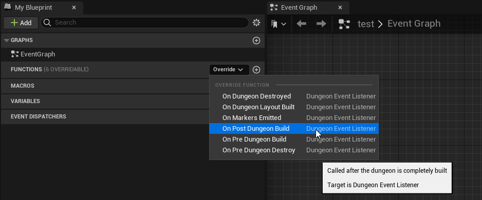
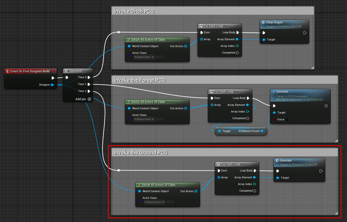
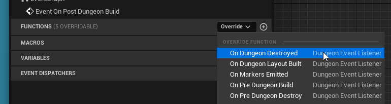
Open it up and override the OnPostDungeonBuilt function
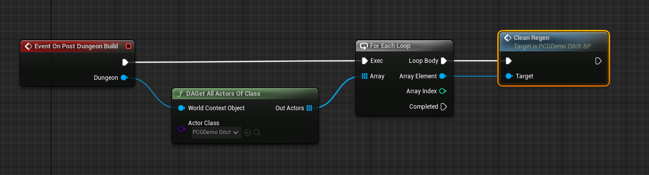
In this function, we’re going to iterate through all the PCGDemo_DitchBP blueprints that were spawned as part of the room module and call the Clean Regen function on it.
Dungeon Architect has a DAGetAllActorsOfClass helper node for this
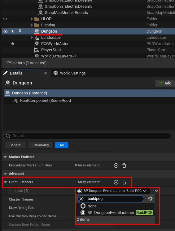
Assign this to the dungeon actor’s Event Listener list
Rebuild the dungeon and it should build the ditch blueprints

Forest PCG Blueprint
Next, drop in a forest PCG bluerpint PCGDemo_ForestBP anywhere on the scene
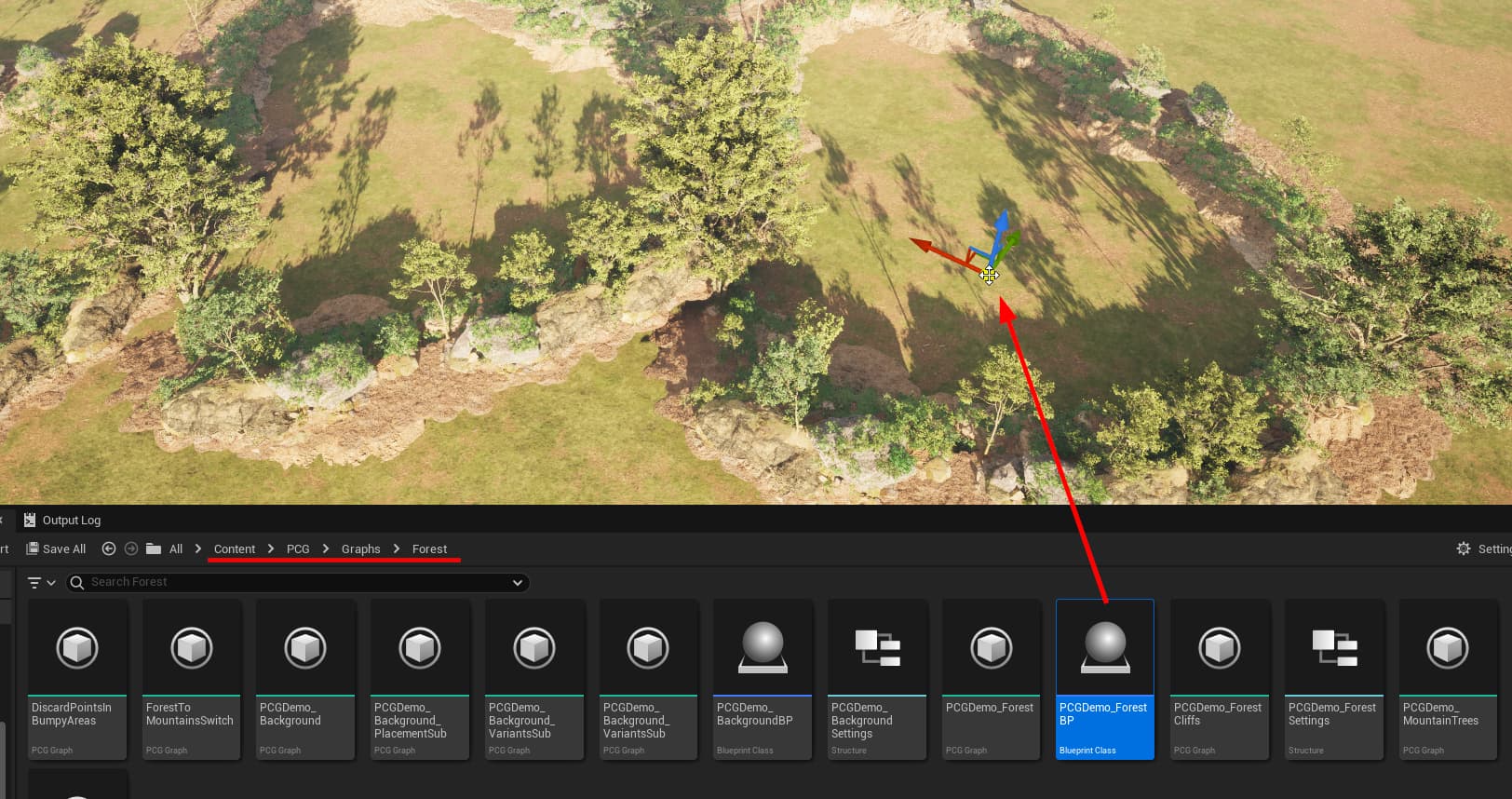
We’ll invoke the Forest PCG bluerpint on our dungeon post build event
Destroy the current dungeon and rebuild the dungeon

Ground PCG Graph
Drop in the Content/PCG/Graphs/Ground/PCGDemo_GroundBP blueprint anywhere on to the scene
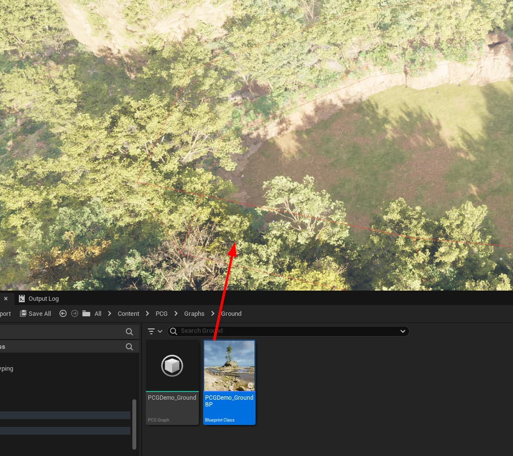
Lets invoke this PCG as well, after our dungeon builds
PCG Post Destroy setup
We want to cleanup and rebuild the forest after the dungeon is destroyed
Override the OnPostDungeonDestroyed functoin
and perform cleanup like this:

Destroying the dungeon should remove the forest


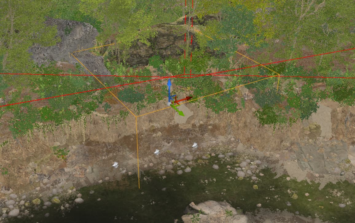
Connection
The adjacent room connections look like this. The geometry from the other room is overlaping

Open up the module and increase the bounds. Also move the connection points outwards (this depends on your art asset placement)
Save and rebuild the module database cache. Then rebuild the dungeon

Opening up connections
Now we need to create a gap so the player can walk through to the other room
The forest and ditch PCG graphs designed by Epic have a logic where generation inside volumes is ignored if that PCGVolume has a PCG_EXCLUDE actor tag
To test this out, drop in a PCGVolume on to the scene
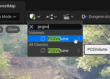
Scale it and place it approximately where the connection is
In the PCGVolume’s detail panel, search for Tag and add PCG_EXCLUDE to the actor tag

NOTE: Do not add this to the component tag. It should be added to the Actor tag as shown in the image above
Destroy and rebuild the dungeon

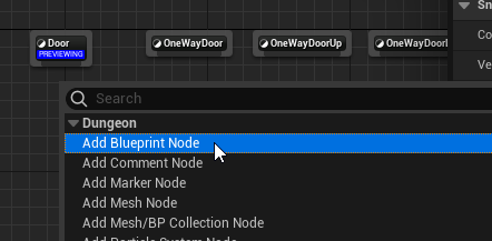
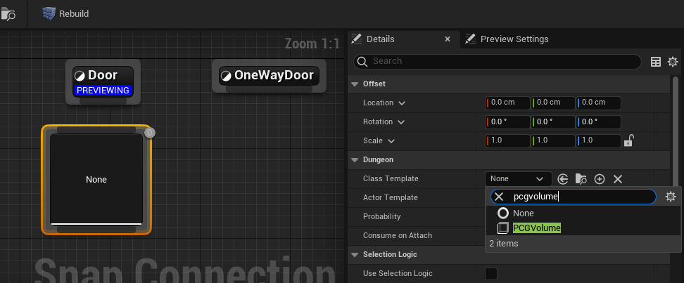
Open up your connection asset and use a PCG volume as a door
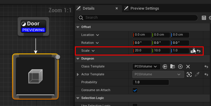
Set the scale to (20, 10, 10)
Set the PCG_EXCLUDE tag in the node template settings

Add more assign assets around the connection opening, like I’ve done in the video to cover up the gaps
